


# Understanding Cutter Compensation on CNC Lathes: A Complete Guide
Cutter compensation is one of the most powerful yet often misunderstood features in CNC lathe programming. If you’ve ever struggled with achieving precise dimensions or wondered why your parts come out slightly oversized or undersized, mastering cutter compensation could be the game-changer you need. In this comprehensive guide, we’ll walk through exactly how cutter compensation works, explore four practical turning examples, and provide you with the knowledge to implement it successfully in your own programs.
## What is Cutter Compensation?
Cutter compensation, often referred to as “cutter comp,” is a CNC feature that automatically adjusts the tool path to account for the cutting tool’s radius or nose radius. Instead of manually calculating offsets for every cut, the CNC control does the math for you, making programming more efficient and flexible.
Think of it as telling the machine: “Here’s the part profile I want, now you figure out where to position the tool to achieve it.” This becomes especially valuable when:
– Using tools with different nose radii
– Making adjustments for tool wear
– Programming complex profiles with multiple angles and radii
– Switching between roughing and finishing operations
## The Foundation: Understanding Tool Tip Directions
Before diving into the G-codes, it’s crucial to understand tool tip directions. On a CNC lathe, tools are classified by their tip orientation, numbered 1 through 8. This numbering system tells the control where the cutting edge is located relative to the tool holder.
### Common Tool Tip Directions:
– **Tip Direction 1**: Boring bar with cutting edge facing up and toward the chuck
– **Tip Direction 2**: Standard boring bar orientation
– **Tip Direction 3**: Outside turning tool, cutting edge down and away from chuck
– **Tip Direction 4**: Outside turning tool for sub-spindle work
The tip direction must be correctly set in your tool offset page for cutter compensation to work properly. Get this wrong, and your compensation will be applied in the wrong direction!
## The G-Code Trinity: G40, G41, and G42
These three G-codes control cutter compensation:
### G40 – Cancel Cutter Compensation
This command turns off cutter compensation. Always use G40 when:
– Completing a compensated tool path
– Before rapid positioning moves
– When changing tools
### G41 – Cutter Compensation Left
Activates compensation with the tool on the left side of the programmed path (when looking in the direction of tool movement). Commonly used for:
– Boring operations
– Left-hand turning operations
– Inside diameter work
### G42 – Cutter Compensation Right
Activates compensation with the tool on the right side of the programmed path. Typically used for:
– Outside diameter turning
– Standard right-hand turning tools
– Most external profiling operations
## The Essential Rules of Cutter Compensation
To successfully implement cutter compensation, follow these critical rules:
### 1. **Activation Must Occur During a Linear Move**
Never activate G41 or G42 during a rapid (G00) move or while the tool is stationary. Always engage compensation during a feed move (G01).
### 2. **Approach from a Safe Position**
Position your tool at least one tool radius away from the part before activating compensation. This gives the control room to calculate and apply the offset.
### 3. **Cancel Before Rapids**
Always cancel compensation (G40) before making rapid moves or tool changes. Failing to do so can cause unexpected tool movements.
### 4. **Use Proper Lead-In and Lead-Out Moves**
Provide straight-line moves when activating and deactivating compensation. Avoid starting or ending compensation on an arc.
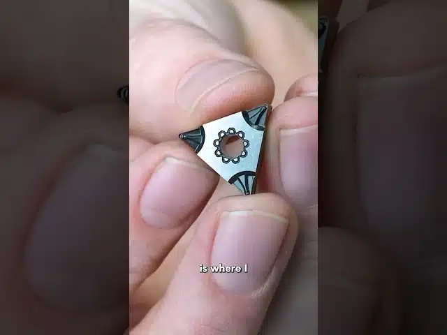
### 5. **Verify Tool Nose Radius Values**
Ensure your tool offset table contains accurate nose radius values. Even small errors here can significantly impact part dimensions.
## Practical Examples from the Program
Let’s analyze the four examples from the provided program:
### Example 1: Rough Turning (Tip Direction 3)
“`gcode
G1G41Z0.F.006 ; Activate left compensation
G1X-.07F.01 ; Face to center
G0G40X2.Z.04 ; Cancel compensation and retract
“`
This shows a facing operation where G41 is used because we’re cutting from outside to center.
### Example 2: Finish Turning with G42
“`gcode
G1G42Z0.F.006 ; Activate right compensation
X.905,R.005 ; Cut with blend radius
X1.,A150.,R.005 ; Angular move with radius
“`
Here, G42 is used for outside diameter finishing, maintaining consistent wall thickness through complex geometry.
### Example 3: Boring with G41 (Tip Direction 2)
“`gcode
G1G41Z0F.006 ; Activate left compensation for boring
X.795,A210. ; Bore with angle
“`
For internal operations, G41 keeps the tool on the correct side of the programmed path.
### Example 4: The Power of the “,A” Command
The program demonstrates the “,A” command for angular moves:
“`gcode
X1.,A150.,R.005 ; Move to X1.0 at 150° angle with .005 radius
“`
This powerful feature allows programming angles directly without calculating endpoints, and cutter compensation handles the tool positioning automatically.
## Best Practices for Success
### 1. **Start Simple**
Begin with basic straight cuts before attempting complex profiles. Master the fundamentals before moving to advanced applications.
### 2. **Use Consistent Programming Methods**
Develop a standard approach for activating and deactivating compensation. Consistency reduces errors.
### 3. **Test with Proven Tools**
When learning, use tools with known, accurate nose radii. This eliminates one variable while troubleshooting.
### 4. **Document Your Approach**
Add clear comments in your programs indicating:
– When compensation is active
– Which direction (G41/G42) is being used
– Tool tip direction numbers
### 5. **Verify with Graphics**
Use your machine’s graphics or simulation software to verify tool paths before cutting metal.
## Common Pitfalls and How to Avoid Them
### Incorrect Tip Direction
Double-check tool tip directions in your offset page. This is the most common cause of compensation working “backwards.”
### Insufficient Clearance
Always approach the part with enough clearance for the control to apply compensation smoothly.
### Forgetting to Cancel
Leaving compensation active during tool changes or program ends can cause crashes. Make G40 a habit.
### Radius Too Large for Geometry
If your tool nose radius exceeds the smallest radius in your part profile, the control may alarm or produce incorrect geometry.
## Advanced Applications
Once you’ve mastered the basics, cutter compensation opens doors to:
– **Dynamic tool wear adjustment**: Modify tool offsets without changing programs
– **Family of parts programming**: Use the same program for similar parts with different dimensions
– **Simplified roughing cycles**: Let compensation handle stock allowances automatically
– **Complex profile machining**: Program the finished profile directly without offset calculations
## Conclusion
Cutter compensation transforms CNC lathe programming from a exercise in complex calculations to an intuitive process of describing what you want to make. By understanding tool tip directions, mastering the G40/G41/G42 commands, and following the essential rules, you’ll produce more accurate parts with less programming effort.
The examples provided demonstrate real-world applications across different operations—from roughing to finishing, external to internal work. Start with these patterns, adapt them to your needs, and gradually build your confidence with more complex applications.
Remember: cutter compensation is a tool that, when properly understood and applied, makes you a more efficient and capable CNC programmer. Take the time to practice these concepts, and you’ll find yourself programming with greater confidence and achieving better results.
Want to dive deeper into CNC programming techniques? Stay tuned for more advanced topics, and don’t hesitate to experiment with the provided program examples. The path to mastery is paved with practice and understanding—cutter compensation is your next step on that journey.
What Should I Do Right Now?
If you’re evaluating new machining processes or equipment, our team can help you determine the best approach for your specific parts, offering guidance, insights, and practical recommendations based on your production needs and goals. Whether you’re optimizing existing workflows or exploring new manufacturing methods, we’re here to support your decision-making.
You Might Also Like
Not Sure If I Was Allowed to Do This on the CNC Machine – CNC Machining Adventure
# Not Sure If I Was Allowed to Do This… But I Did It Anyway on the CNC Every machinist has had that moment —…
CNC Machining Cost Reduction: Can This Strategy Cut Costs by 56%?
# IF This Works, It Will Cut Costs by 56%: A Bold CNC Machining Experiment In the world of CNC machining, the difference between profitability…
How Many of You Have Done This? Common CNC Machining Mistakes Every Machinist Can Relate To
# How Many of You Have Done This? A CNC Machining Moment We Can All Relate To If you’ve spent any amount of time in…